LTE is a standard for wireless data communications technology and an evolution of the GSM/UMTS standard. The main goals of LTE is to increase the capacity and data rates of wireless data networks, improve spectrum efficiency, improve coverage, reduced latency and packet-optimized system that support mutliple Radio Access. Thus, in order to achieve the goals, the architecture of the network if different from the previous wireless data transfer network, GPRS. So, in post, a comprehensive overview of the network architecture and basic working principle of LTE network is going to be discussed.
Basically, the LTE standard only supports packet switching with its all-IP network. The reason why LTE is designed only for packet switching is because it aims to provide seamless Internet Protocol (IP) connectivity between user equipment (UE) and the packet data network (PDN), without any disruption to the end users’ applications during mobility. Due to this characteristic, voice calls and text message natively (which are typically handled by circuit-switched networks like GSM and CDMA). In LTE architecture, Evolved UTRAN (E-UTRAN) is an important role which is the air interface of LTE upgrade path for mobile networks meanwhile it is accompanied by an evolution of the non-radio aspects under the term "System Architecture Evolution" (SAE), which includes the Evolved Packet Core (EPC) network. Together LTE and SAE comprise the Evolved Packet System (EPS). Besides that, LTE network uses an eNodeB (evolved node B, essentially an LTE base station), a MME (Mobile management entity), a HSS (home subscriber server), a SGW (serving gateway), and a PGW (a packet data network gateway). These are considered as part of the EPC except eNodeB.
 |
First, let us look into EPS in detail, the following figure showing those elements in EPS network.
 |
In LTE, main function of EPS is to provide the user with IP connectivity to a PDN for accessing the Internet, as well as for running service such as Voice over IP (VoIP). An EPS bearer is typically associated with a QoS. Multiple bearers can be established for a user in order to provide different Qos streams or connectivity to different PDNs. Figure above shows the overall network architecture, including the network elements and the standardized interfaces. At a high level, the network is comprised of the CN (EPC) and the access network E-UTRAN. While the CN consists of many logical nodes, the access network is made up of essentially just one node, the evolved NodeB (eNodeB), which connects to the UEs. Each of these network elements is interconnected by means of interfaces that are standardized in order to allow multi-vendor interoperability. This gives network operators the possibility to source different network elements from different vendors. In fact, network operators may choose in their physical implementations to split or merge these logical network elements depending on commercial considerations.
The core network (called EPC in SAE) is responsible for the overall control of the UE and establishment
of the bearers. The main logical nodes of the EPC are:
• PDN Gateway (P-GW)
• Serving Gateway (S-GW)
• Mobility Management Entity (MME)
In addition to these nodes, EPC also includes other logical nodes and functions such as the Home Subscriber Server (HSS) and the Policy Control and Charging Rules Function (PCRF). HSS which contains users’ SAE subscription data such as the EPS-subscribed QoS profile and holds those information about the PDNs to which the user can connect, while PCRF is responsible for policy control decision-making, as well as for controlling the flow-based charging functionalities in the Policy Control Enforcement Function (PCEF), which resides in the P-GW. From the figure above, MME which is the control node that processes the signaling between the UE and the CN. The protocols running between the UE and the CN are known as the Non Access Stratum (NAS) protocols.
The main functions supported by the MME can be classified as:
• Functions related to bearer management – This includes the establishment, maintenance and release
of the bearers and is handled by the session management layer in the NAS protocol.
• Functions related to connection management – This includes the establishment of the connection and
security between the network and UE and is handled by the connection or mobility management
layer in the NAS protocol layer.
The access network of LTE, E-UTRAN, simply consists of a network of eNodeBs.For normal user traffic (as opposed to broadcast), there is no centralized controller in E-UTRAN; hence the E-UTRAN architecture is said to be flat. The eNodeBs are normally interconnected with each other by means of an
interface known as “X2” and to the EPC by means of the S1 interface — more specifically, to the MME by means of the S1-MME interface and to the S-GW by means of the S1-U interface. The protocols that run between the eNodeBs and the UE are known as the “AS protocols"

The E-UTRAN is responsible for all radio-related functions, which can be summarized briefly as:
• Radio resource management (RRM) – This covers all functions related to the radio bearers, such
as radio bearer control, radio admission control, radio mobility control, scheduling and dynamic
allocation of resources to UEs in both uplink and downlink.
• Header Compression – This helps to ensure efficient use of the radio interface by compressing
the IP packet headers that could otherwise represent a significant overhead, especially for small
packets such as VoIP.
• Security – All data sent over the radio interface is encrypted.
• Connectivity to the EPC – This consists of the signaling toward MME and the bearer path
toward the S-GW.
For roaming architecture, it is shown as below:

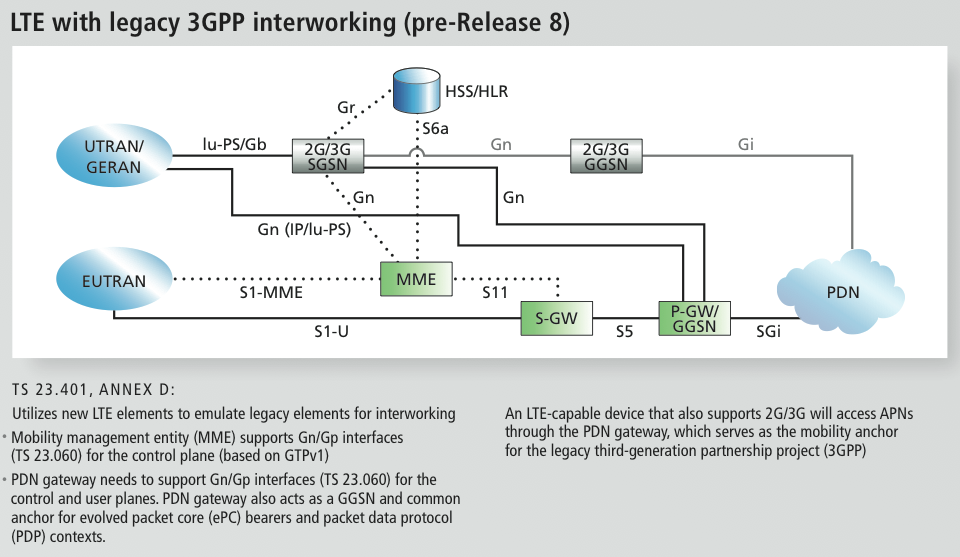
For interworking architecture, it is shown as below:
Here is a video which briefly explain the overview of architecture of whole LTE network.
0 comments :
Post a Comment